Difference between revisions of "MAME Cabinet"
| (48 intermediate revisions by 3 users not shown) | |||
| Line 1: | Line 1: | ||
| + | '''MAME''', an acronym that stands for Multiple Arcade Machine Emulator, is an emulator designed to reproduce older arcade system hardware via software on a modern personal computer. | ||
| + | |||
{{Infobox project | {{Infobox project | ||
| − | |project_name = MAME Cabinet | + | |project_name = MMMAME <br>(Midsouth Makers MAME Cabinet) |
| − | |image = | + | |image = MAME Cabinet v2.0 Sanded.jpg |
| − | |caption = | + | |caption = Sanded cabinet and gutted |
| − | |owner = critter42 | + | |owner = Group |
| − | |version = | + | |lead = [[User:critter42|critter42]] & MemphisArtGuy |
| + | |version = 2.0 | ||
|status = inprogress | |status = inprogress | ||
| − | |start_date = | + | |start_date = November 2012 |
|cost = Free | |cost = Free | ||
}} | }} | ||
| − | == | + | == TODO List == |
| − | === | + | *Spray paint the rest of the base colors before laying down the vinyl paint mask. |
| − | + | *Lay the vinyl and paint the cabinet black. | |
| + | *Lay out and make the joystick/button panel | ||
| + | *Mount and wire the controller board to the panel | ||
| + | *Purchase/Paint a 2'x4' 1/2 sheet of plywood for the back of the cabinet. | ||
| + | |||
| + | |||
| + | |||
| + | == Design == | ||
| + | === Computer === | ||
| + | *HP Compaq DC7600 Convertible Minitower PC 3.2 GHZ | ||
| + | *OS [http://www.ubuntu.com/ Ubuntu] 12.04 | ||
| + | *2 HDD on SATA BUS - Roms Drive - OS Drive | ||
| + | *WIFI Adapter : ENUWI-G2 802.11 B/G | ||
| + | *1Gb DDR2 - Would like to upgrade to 4Gb | ||
| + | *19inch 3:4 LCD | ||
| + | |||
| + | === Display === | ||
| + | *Samsung 19inch 930B | ||
| + | |||
| + | === Audio === | ||
| + | *On Board | ||
| + | |||
| + | === Software === | ||
| + | *'''Preferred Interface:''' [http://www.cabrio-fe.org/ Cabrio] | ||
| + | *'''Secondary Interface:''' [http://gmameui.sourceforge.net/ GMAMEUI] | ||
| + | *'''Mame Software:''' [http://sdlmame.wallyweek.org/download/ sdlmame] | ||
| + | |||
| + | === Controls === | ||
| + | The Williams Defender cabinet shared the "base cabinet" with many other games like Joust and Sinistar. This fact makes it very easy to make multiple control decks. The control decks dimensions are 23 1/2 inches by 8 inches made of 3/4 plywood. | ||
| − | + | We have a few leftover parts from the last MAME project, also ordered a set of [http://www.ebay.com/itm/360450175737 buttons and joysticks] form Ebay seller TwistedQuarter for $29.99 plus $10 shipping as a donation. | |
| − | + | <strike>Danny is currently running a custom firmware on an Arduino Uno and checking the results of that.</strike> '''Interface was too laggy''' | |
| − | |||
| − | {{ | + | === Graphics === |
| − | |title = | + | ==== Side Stencils ==== |
| − | |width = | + | {{Gallery |
| − | |height = | + | |title = Stencils |
| − | |File: | + | |width=160 |
| − | |File: | + | |height=170 |
| − | |File: | + | |lines=1 |
| − | |File: | + | |File:Mame stencil little gear.svg| Little Top Gear |
| + | |File:Mame stencil big gear.svg|alt2=Bottom gear| Big Bottom Gear | ||
| + | |File:Mame stencil iron.svg|alt3=Soldering Iron| Soldering Iron | ||
| + | |File:Mame stencil wrench.svg|alt3=Wrench| Wrench | ||
}} | }} | ||
| − | == | + | == Custom Electronics for the Controls == |
| − | The | + | |
| + | A custom board was fabricated for controlling the buttons and joysticks [http://vusb.wikidot.com/project:mamepanel V-USB MAMEPanel] was ported to work for the Atmel atmega644p micro controller. The hardware currently emulates 2 joysticks with 8 buttons each and a keyboard hid device. MAMEPanel is expandable to 3 joysticks and a mouse input is also possible. Hardware has only been tested with windows built in tool for testing joysticks, real world performance is still to be determined. It should be fine since it is based on a working and tested design. Below is the current keymap and schematic. | ||
| − | + | [[File:V-USB_Mame_Panel_Atmega32-Schematic.png|thumb|center|Schematic]] | |
| − | {{ | + | <nowiki> |
| − | |title = MAME Cabinet | + | // Atmega32 Shift switch off |
| − | |width = | + | PROGMEM const unsigned char NormalMapping[NUMBER_OF_INPUTS] = |
| − | |height = | + | { // Pin Atmega Board Function |
| − | |File:MAME | + | KEY_5, // 40 PA0 X6-1 COINTRIGGER |
| − | |File: | + | 0, // 39 PA1 X4-8 none |
| − | |File: | + | 0, // 38 PA2 X4-7 none |
| − | |File: | + | KEY_2, // 37 PA3 X4-6 JOY2START |
| + | KEY_1, // 36 PA4 X4-5 JOY1START | ||
| + | J1_Button8, // 35 PA5 X4-4 JOY1BUTTON8 | ||
| + | J1_Button7, // 34 PA6 X4-3 JOY1BUTTON7 | ||
| + | J1_Button6, // 33 PA7 X4-2 JOY1BUTTON6 | ||
| + | 0, // 1 PB0 X9-2 SHIFTSWITCH | ||
| + | J2_Button8, // 2 PB1 X7-1 JOY2BUTTON8 | ||
| + | J2_Button7, // 3 PB2 X7-2 JOY2BUTTON7 | ||
| + | J2_Button6, // 4 PB3 X8-1 JOY2BUTTON6 | ||
| + | J2_Button5, // 5 PB4 X8-2 JOY2BUTTON5 | ||
| + | J2_Button4, // 6 PB5 X5-1 JOY2BUTTON4 | ||
| + | J2_Button3, // 7 PB6 X5-2 JOY2BUTTON3 | ||
| + | J2_Button2, // 8 PB7 X5-3 JOY2BUTTON2 | ||
| + | J1_Up, // 22 PC0 X3-2 JOY1UP | ||
| + | J1_Left, // 23 PC1 X3-3 JOY1LEFT | ||
| + | J1_Right, // 24 PC2 X3-4 JOY1RIGHT | ||
| + | J1_Button1, // 25 PC3 X3-5 JOY1BUTTON1 | ||
| + | J1_Button2, // 26 PC4 X3-6 JOY1BUTTON2 | ||
| + | J1_Button3, // 27 PC5 X3-7 JOY1BUTTON3 | ||
| + | J1_Button4, // 28 PC6 X3-8 JOY1BUTTON4 | ||
| + | J1_Button5, // 29 PC7 X4-1 JOY1BUTTON5 | ||
| + | J2_Button1, // 15 PD1 X5-4 JOY2BUTTON1 | ||
| + | J2_Right, // 17 PD3 X5-5 JOY2RIGHT | ||
| + | J2_Left, // 18 PD4 X5-6 JOY2LEFT | ||
| + | J2_Up, // 19 PD5 X5-7 JOY2UP | ||
| + | J2_Down, // 20 PD6 X5-8 JOY2DOWN | ||
| + | J1_Down // 21 PD7 X3-1 JOY1DOWN | ||
| + | }; | ||
| + | |||
| + | // Atmega32 Shift switch on | ||
| + | PROGMEM const unsigned char ShiftMapping[NUMBER_OF_INPUTS]= | ||
| + | { // Pin Atmega Board Function | ||
| + | KEY_5, // 40 PA0 X6-1 COINTRIGGER | ||
| + | 0, // 39 PA1 X4-8 none | ||
| + | 0, // 38 PA2 X4-7 none | ||
| + | AC_Mute, // 37 PA3 X4-6 JOY2START | ||
| + | KEY_P, // 36 PA4 X4-5 JOY1START | ||
| + | 0, // 35 PA5 X4-4 JOY1BUTTON8 | ||
| + | 0, // 34 PA6 X4-3 JOY1BUTTON7 | ||
| + | 0, // 33 PA7 X4-2 JOY1BUTTON6 | ||
| + | 0, // 1 PB0 X9-2 SHIFTSWITCH | ||
| + | 0, // 2 PB1 X7-1 JOY2BUTTON8 | ||
| + | 0, // 3 PB2 X7-2 JOY2BUTTON7 | ||
| + | 0, // 4 PB3 X8-1 JOY2BUTTON6 | ||
| + | 0, // 5 PB4 X8-2 JOY2BUTTON5 | ||
| + | 0, // 6 PB5 X5-1 JOY2BUTTON4 | ||
| + | KM_ALT_F4, // 7 PB6 X5-2 JOY2BUTTON3 | ||
| + | KM_SHIFT_F7, // 8 PB7 X5-3 JOY2BUTTON2 | ||
| + | KEY_UpArrow, // 22 PC0 X3-2 JOY1UP | ||
| + | KEY_LeftArrow, // 23 PC1 X3-3 JOY1LEFT | ||
| + | KEY_RightArrow, // 24 PC2 X3-4 JOY1RIGHT | ||
| + | KEY_Enter, // 25 PC3 X3-5 JOY1BUTTON1 | ||
| + | KEY_Esc, // 26 PC4 X3-6 JOY1BUTTON2 | ||
| + | KEY_Tab, // 27 PC5 X3-7 JOY1BUTTON3 | ||
| + | 0, // 28 PC6 X3-8 JOY1BUTTON4 | ||
| + | 0, // 29 PC7 X4-1 JOY1BUTTON5 | ||
| + | KEY_F7, // 15 PD1 X5-4 JOY2BUTTON1 | ||
| + | AC_VolumeUp, // 17 PD3 X5-5 JOY2RIGHT | ||
| + | AC_VolumeDown, // 18 PD4 X5-6 JOY2LEFT | ||
| + | KEY_PageUp, // 19 PD5 X5-7 JOY2UP | ||
| + | KEY_PageDown, // 20 PD6 X5-8 JOY2DOWN | ||
| + | KEY_DownArrow // 21 PD7 X3-1 JOY1DOWN | ||
| + | }; | ||
| + | |||
| + | </nowiki> | ||
| + | |||
| + | == Cosmetics == | ||
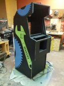
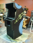
| + | *'''Cabinet''' — The cabinet will be black with green and blue artwork. Spray paint was purchase by Danny and Ben | ||
| + | *'''T-molding''' — will also be black and has been purchased by Dan | ||
| + | |||
| + | == Gallery == | ||
| + | {{Gallery | ||
| + | |title = MAME Cabinet | ||
| + | |width=160 | ||
| + | |height=170 | ||
| + | |lines=2 | ||
| + | |File:MAME_1.jpg|alt1=Monitor mounted|New monitor mounted | ||
| + | |File:MAME_4.jpg|alt1=Sanded sideview of cabinet | Sanded side | ||
| + | |File:MAME_2.jpg|alt2=Danny and Dan measuring for acceptable artwork sizes|Measuring or acceptable artwork sizes | ||
| + | |File:Mame side layout.svg|alt3=Mame Cabinet artwork, contains several large gears, wrench that says makers, and a soldering iron| MAME Artwork | ||
| + | |File:MAME_3.jpg|alt3=Dan prepping the vinyl stencil of a soldering iron for one side| Prepping vinyl stencil | ||
| + | |File:MAME_5.jpg|alt3=Big piece of vinyl cut for making side stencils| One of the stencils | ||
| + | |File:MAME_6.jpg|alt3=Weeding the big wrench stencil| Weeding the big wrench | ||
| + | |File:Cabinet1stCoatColor.jpg|alt3=Cabinet after first color base coat| Cabinet after first color base coat | ||
| + | |File:LeftSideStencils.jpg|alt3=Left side, 2nd base color coat and stencils applied| Left side, 2nd base color coat and stencils applied | ||
| + | |File:RightSideStencils.jpg|alt3=Right side, 2nd base color coat and stencils applied| Right side, 2nd base color coat and stencils applied | ||
| + | |File:LeftSideBlack.jpg|alt3=Left side after black topcoat| Left side after black topcoat | ||
| + | |File:RightSideBlack.jpg|alt3=Right side after black topcoat| Right side after black topcoat | ||
| + | |File:LeftSideFinal.jpg|alt3=Left side after removing stencils| Left side after removing stencils | ||
| + | |File:RightSideFinal.jpg|alt3=Right side after removing stencils| Right side after removing stencils | ||
}} | }} | ||
| − | == | + | == Bill of Materials == |
| − | == | + | *DC7600 |
| − | + | *Samsung 19 inch 930b LCD | |
| − | + | *Defender Arcade Cabinet | |
| − | + | ||
| + | == Contributors == | ||
| + | *Ben | ||
| + | *Dan | ||
| + | *Danny | ||
| + | *Dru | ||
| + | *Mark | ||
| − | == | + | == External Links == |
| + | [http://www.cabrio-fe.org/ Cabrio]<br> | ||
| + | [http://www.practicalarduino.com/projects/virtual-usb-keyboard/ Virtual HID Keyboard]<br> | ||
| + | [http://code.rancidbacon.com/ProjectLogArduinoUSB/ Arduino USB Sheild]<br> | ||
| + | [http://www.pjrc.com/teensy/usb_keyboard.html Teensy HID Keyboard]<br> | ||
| + | [http://mitchtech.net/arduino-usb-hid-keyboard/ Arduino Uno HID Keyboard]<br> | ||
| − | == | + | == References == |
| + | {{reflist}} | ||
Latest revision as of 02:43, 17 February 2013
MAME, an acronym that stands for Multiple Arcade Machine Emulator, is an emulator designed to reproduce older arcade system hardware via software on a modern personal computer.
| MMMAME (Midsouth Makers MAME Cabinet) | |
|---|---|
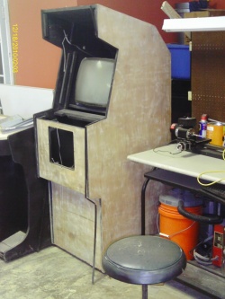
Sanded cabinet and gutted | |
| Information | |
| Owner | Group |
| Lead | critter42 & MemphisArtGuy |
| Version | 2.0 |
| Status | In Progress |
| Started On | November 2012 |
| Cost | Free |
TODO List
- Spray paint the rest of the base colors before laying down the vinyl paint mask.
- Lay the vinyl and paint the cabinet black.
- Lay out and make the joystick/button panel
- Mount and wire the controller board to the panel
- Purchase/Paint a 2'x4' 1/2 sheet of plywood for the back of the cabinet.
Design
Computer
- HP Compaq DC7600 Convertible Minitower PC 3.2 GHZ
- OS Ubuntu 12.04
- 2 HDD on SATA BUS - Roms Drive - OS Drive
- WIFI Adapter : ENUWI-G2 802.11 B/G
- 1Gb DDR2 - Would like to upgrade to 4Gb
- 19inch 3:4 LCD
Display
- Samsung 19inch 930B
Audio
- On Board
Software
Controls
The Williams Defender cabinet shared the "base cabinet" with many other games like Joust and Sinistar. This fact makes it very easy to make multiple control decks. The control decks dimensions are 23 1/2 inches by 8 inches made of 3/4 plywood.
We have a few leftover parts from the last MAME project, also ordered a set of buttons and joysticks form Ebay seller TwistedQuarter for $29.99 plus $10 shipping as a donation.
Danny is currently running a custom firmware on an Arduino Uno and checking the results of that. Interface was too laggy
Graphics
Side Stencils
| Stencils | |||||||||
| |||||||||
Custom Electronics for the Controls
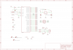
A custom board was fabricated for controlling the buttons and joysticks V-USB MAMEPanel was ported to work for the Atmel atmega644p micro controller. The hardware currently emulates 2 joysticks with 8 buttons each and a keyboard hid device. MAMEPanel is expandable to 3 joysticks and a mouse input is also possible. Hardware has only been tested with windows built in tool for testing joysticks, real world performance is still to be determined. It should be fine since it is based on a working and tested design. Below is the current keymap and schematic.
// Atmega32 Shift switch off
PROGMEM const unsigned char NormalMapping[NUMBER_OF_INPUTS] =
{                       //  Pin Atmega  Board   Function
    KEY_5,              //  40  PA0     X6-1    COINTRIGGER
    0,                  //  39  PA1     X4-8    none
    0,                  //  38  PA2     X4-7    none
    KEY_2,              //  37  PA3     X4-6    JOY2START
    KEY_1,              //  36  PA4     X4-5    JOY1START
    J1_Button8,         //  35  PA5     X4-4    JOY1BUTTON8
    J1_Button7,         //  34  PA6     X4-3    JOY1BUTTON7
    J1_Button6,         //  33  PA7     X4-2    JOY1BUTTON6
    0,                  //   1  PB0     X9-2    SHIFTSWITCH
    J2_Button8,         //   2  PB1     X7-1    JOY2BUTTON8
    J2_Button7,         //   3  PB2     X7-2    JOY2BUTTON7
    J2_Button6,         //   4  PB3     X8-1    JOY2BUTTON6
    J2_Button5,         //   5  PB4     X8-2    JOY2BUTTON5
    J2_Button4,         //   6  PB5     X5-1    JOY2BUTTON4
    J2_Button3,         //   7  PB6     X5-2    JOY2BUTTON3
    J2_Button2,         //   8  PB7     X5-3    JOY2BUTTON2
    J1_Up,              //  22  PC0     X3-2    JOY1UP
    J1_Left,            //  23  PC1     X3-3    JOY1LEFT
    J1_Right,           //  24  PC2     X3-4    JOY1RIGHT
    J1_Button1,         //  25  PC3     X3-5    JOY1BUTTON1
    J1_Button2,         //  26  PC4     X3-6    JOY1BUTTON2
    J1_Button3,         //  27  PC5     X3-7    JOY1BUTTON3
    J1_Button4,         //  28  PC6     X3-8    JOY1BUTTON4
    J1_Button5,         //  29  PC7     X4-1    JOY1BUTTON5
    J2_Button1,         //  15  PD1     X5-4    JOY2BUTTON1
    J2_Right,           //  17  PD3     X5-5    JOY2RIGHT
    J2_Left,            //  18  PD4     X5-6    JOY2LEFT
    J2_Up,              //  19  PD5     X5-7    JOY2UP
    J2_Down,            //  20  PD6     X5-8    JOY2DOWN
    J1_Down             //  21  PD7     X3-1    JOY1DOWN
};

// Atmega32 Shift switch on
PROGMEM const unsigned char ShiftMapping[NUMBER_OF_INPUTS]=
{                       //  Pin Atmega  Board   Function
    KEY_5,              //  40  PA0     X6-1    COINTRIGGER
    0,                  //  39  PA1     X4-8    none
    0,                  //  38  PA2     X4-7    none
    AC_Mute,            //  37  PA3     X4-6    JOY2START
    KEY_P,              //  36  PA4     X4-5    JOY1START
    0,                  //  35  PA5     X4-4    JOY1BUTTON8
    0,                  //  34  PA6     X4-3    JOY1BUTTON7
    0,                  //  33  PA7     X4-2    JOY1BUTTON6
    0,                  //   1  PB0     X9-2    SHIFTSWITCH
    0,                  //   2  PB1     X7-1    JOY2BUTTON8
    0,                  //   3  PB2     X7-2    JOY2BUTTON7
    0,                  //   4  PB3     X8-1    JOY2BUTTON6
    0,                  //   5  PB4     X8-2    JOY2BUTTON5
    0,                  //   6  PB5     X5-1    JOY2BUTTON4
    KM_ALT_F4,          //   7  PB6     X5-2    JOY2BUTTON3
    KM_SHIFT_F7,        //   8  PB7     X5-3    JOY2BUTTON2
    KEY_UpArrow,        //  22  PC0     X3-2    JOY1UP
    KEY_LeftArrow,      //  23  PC1     X3-3    JOY1LEFT
    KEY_RightArrow,     //  24  PC2     X3-4    JOY1RIGHT
    KEY_Enter,          //  25  PC3     X3-5    JOY1BUTTON1
    KEY_Esc,            //  26  PC4     X3-6    JOY1BUTTON2
    KEY_Tab,            //  27  PC5     X3-7    JOY1BUTTON3
    0,                  //  28  PC6     X3-8    JOY1BUTTON4
    0,                  //  29  PC7     X4-1    JOY1BUTTON5
    KEY_F7,             //  15  PD1     X5-4    JOY2BUTTON1
    AC_VolumeUp,        //  17  PD3     X5-5    JOY2RIGHT
    AC_VolumeDown,      //  18  PD4     X5-6    JOY2LEFT
    KEY_PageUp,         //  19  PD5     X5-7    JOY2UP
    KEY_PageDown,       //  20  PD6     X5-8    JOY2DOWN
    KEY_DownArrow       //  21  PD7     X3-1    JOY1DOWN
};
Cosmetics
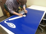
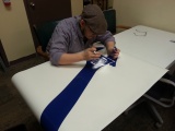
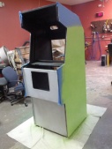
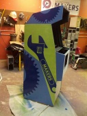
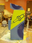
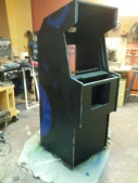
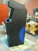
- Cabinet — The cabinet will be black with green and blue artwork. Spray paint was purchase by Danny and Ben
- T-molding — will also be black and has been purchased by Dan
Gallery
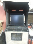
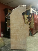
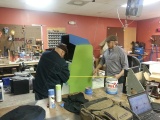
| MAME Cabinet | ||||||||||||||||||||||||||||
| ||||||||||||||||||||||||||||
Bill of Materials
- DC7600
- Samsung 19 inch 930b LCD
- Defender Arcade Cabinet
Contributors
- Ben
- Dan
- Danny
- Dru
- Mark
External Links
Cabrio
Virtual HID Keyboard
Arduino USB Sheild
Teensy HID Keyboard
Arduino Uno HID Keyboard


